Machine Vision Lighting Techniques: How to Cut False Rejects Below 1%
Your automated inspection system did not reject 120 machined valve bodies this morning because of tool chatter or dimensional drift. It kicked them off the conveyor because 9:15 AM sunlight hit the eastern factory skylight at an angle your neural network never saw during offline testing.
On active factory floors, sloppy machine vision lighting techniques create baseline false reject rates between 5% and 15%. That artificial defect spike jams manual rework stations, burns through unit margins, and turns every weekly review between quality heads and plant managers into an argument.
Whenever an automated inspection line starts dumping good parts into scrap bins, the software team's default reflex is to open up PyTorch, drop the confidence threshold to 0.4, or harvest another 20,000 synthetic training images. It's a waste of time. Over 80% of computer vision failures on active assembly lines have nothing to do with neural network architectures or model weights, they happen because of bad photon delivery. When a hot spot blows out a cluster of pixels to pure saturation (255, 255, 255), the spatial data inside that patch is gone. No downstream deep learning model can extract features from information that never hit the sensor in the first place.
Why Do Factory Vision Systems Suffer From High False Reject Rates?
Factory vision systems suffer from high false reject rates because ambient illumination changes throughout the day while workpiece surfaces scatter light unpredictably into the camera lens. Sunlight from roof skylights, moving overhead gantry cranes, and shifting tooling marks introduce uncontrolled photons that camera sensors register as surface anomalies. When an optical setup fails to create high contrast between a real defect and the background material, the visual inspection system misclassifies acceptable parts as defective scrap.
Industrial benchmarks from UnitX and Oxmaint show baseline false reject rates on conventional optical inspection lines hovering between 5% and 15%. Across hundreds of field rollouts, plants routinely eat an average 23-point collapse in accuracy between the vendor's clean bench demo (98%) and the reality of the plant floor (75%).
That 23-point cliff is rarely an algorithmic failure. In a vendor's demo lab, parts sit pristine, motionless, and dead-center in a climate-controlled room under dialed-in LED arrays. On your line, those exact parts roll in sweating machining coolant, vibrating at high speed across a rattling belt, directly underneath flickering high-bay lights.
When raw specular glare hits an unpolarized lens, the sensor clips. Your convolutional neural network reads that burned-out hotspot as an edge, a tear, or a porosity defect. Meanwhile, directional shadows cast by generic overhead shop lights bury hairline fractures, letting bad parts pass inspection. You don't fix false rejects by retraining your models; you fix them by locking down the physics of the scene before light ever touches the sensor.
The Optical Geometry Fallacy: Why More Light Degrades Defect Contrast
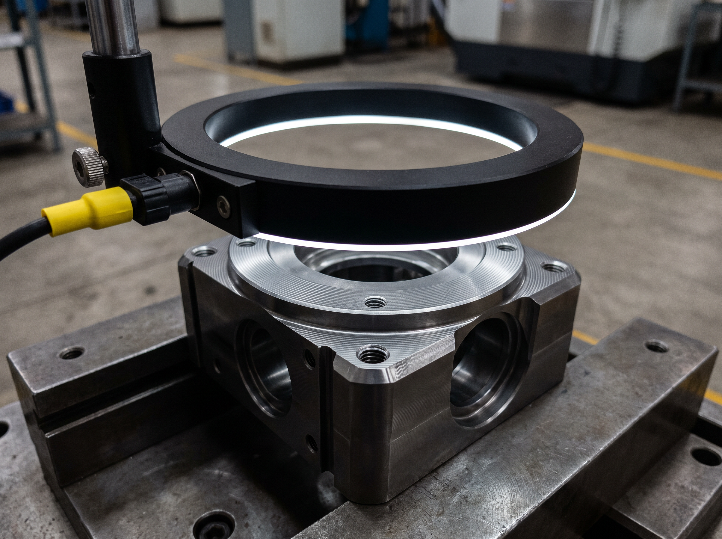 Low-angle optical geometry illuminates hairline surface defects without creating saturated pixel blowouts.
The most common mistake on a shop floor is assuming that a noisy, low-contrast image just needs a bigger lamp. When an inspection camera misses micro-scratches on polished aluminum or gloss plastics, the immediate technician response is to pull a 10-watt ring light and bolt on a 50-watt floodlight.
It almost always makes the image worse. Cranking up light intensity on machined metal or injection-molded resin destroys defect contrast. Direct, high-output illumination creates blinding specular glare that matches or swamps the intensity of the actual flaw. Machine vision runs on signal-to-noise ratio: the defect has to bounce photons into the lens while the background sends them away, or vice versa. Flooding your field of view with uncollimated light just jacks up the noise floor across the entire pixel array.
Controlling defect visibility is purely a function of incident angle, how incoming rays strike the part geometry relative to your optical axis. The machine vision lighting market cleared $1.84 billion in 2024 and is on track for $3.55 billion by 2032, according to industrial sensor research. That capital isn't going into brighter white bulbs; it is going into narrow-band strobes, matched bandpass filters, and high-frequency controllers built to isolate physical geometry at line speed.
Low-Angle Dark-Field Illumination (10° to 15°)
Standard bright-field lighting points photons straight down into the field of view, bouncing specular reflections right back down the barrel of the lens. Dark-field lighting does the inverse.
Drop an LED ring or line array down to a grazing angle of 10° to 15° relative to the part face. Every primary specular reflection skips cleanly off the surface and flies past the lens. To the sensor, a spotless, mirror-finished steel block renders as pure black velvet. But the second a burr, scratch, or pit breaks that flat plane, those microscopic raised edges catch the grazing rays and scatter photons straight up into the camera.
You get crisp, absolute contrast: blinding white defect pixels against an ink-black field. Instead of asking an edge-detection model to hunt for faint gray-value shifts against machined milling lines, low-angle dark-field geometry turns micro-fractures into binary signals.
Coaxial Illumination and Beam-Splitters
If you're inspecting planar, mirror-like surfaces, semiconductor wafers, polished battery foils, or lapped stainless plates, ring lights leave an unusable, blown-out donut reflection right in the middle of your frame. Dark-field geometry fails here too if you need to see down inside tight bores or deep machined pockets.
Coaxial lighting handles this with an internal emitter mounted perpendicular to your optical train and a 50/50 beam-splitter glass pinned at 45°. Light shoots sideways into the splitter, drops straight down through the lens axis, hits the workpiece at a perfect 90° angle, and bounces straight back up through the glass into the sensor grid.
Anything flat, level, and true shows up as solid, uniform white. Any scratch, pit, or warped edge scatters rays away from the return path and shows up as a razor-sharp black silhouette. Coaxial optics convert mirror-finish headaches into flat, predictable fields, letting our YOLOv8 models flag 20-micron defects without tripping on room glare.
Diffuse Dome Illumination and Cross-Polarization
Curved specular parts, drawn aluminum cans, bearing sleeves, threaded studs, toss light in every direction at once. Bolt a standard ring light over them and you get blinding hotspots that white out entire quadrants of your sensor.
A diffuse dome fixes this by firing LEDs upward into a coated hemispherical bowl, bouncing scattered, omnidirectional light back down over the component from every angle. It washes out directional shadows and swallows hot spots whole.
When you're running high-gloss blister packs or flexible clear laminates, even a dome light can leave a milky surface haze. Cross-polarization cuts right through it:
- Polarize the source: Place a linear polarizing sheet over your LED array so every emitted photon vibrates in a single orientation.
- Polarize the sensor: Thread a second linear polarizer onto your lens, clocking it exactly 90° against the emitter sheet.
- Kill the surface glare: Photons that glance off the outer shiny film retain their polarization angle and slam straight into an optical wall at the lens filter.
- Read subsurface features: Light that punches through the film and scatters off the tablet or underlying print loses its polarization, passes the lens, and registers as a clean, glare-free image.
What Machine Vision Lighting Techniques Work Best for High-Speed Inspection Lines?
High-speed inspection lines require narrow-band LED strobing synchronized with ultra-short camera exposure times and high-frequency lighting controllers. Running an inspection line at 120 items/minute or faster causes motion blur if the lighting relies on continuous illumination. Strobing high-output LEDs at overdrive currents, timed precisely to hardware triggers from optical encoders, freezes fast-moving parts in place. Combining strobed LEDs with bandpass optical filters centered on the exact illumination wavelength eliminates factory ambient light variations while maintaining sharp defect edges.
Across our own plant floor rollouts, hitting 99.2% accuracy and a 94% drop in QC errors on 120 items/minute lines came down to treating lighting as a hardware trigger mechanism, not a passive bulb. Running sub-second inference on an industrial edge box is pointless if your input tensor is smeared with five pixels of conveyor blur.
+-----------------------------------------------------------------------------+
| OPTICAL SETUP CHECKLIST FOR HIGH-SPEED LINES                                |
|                                                                             |
| 1. Exposure matching: Set sensor exposure under 50 microseconds.             |
| 2. Overdrive strobing: Pulse LEDs at 300% to 500% nominal current.           |
| 3. Bandpass filtering: Match physical lens filter to the LED peak (e.g. 630nm)|
| 4. Telecentric optics: Eliminate perspective distortion on dimensional checks|
+-----------------------------------------------------------------------------+
When an automated line is flying, continuous factory lamps can't compete with the microscopic shutter speeds you need. Overdriving your LEDs at 300% to 500% of their continuous current rating for 20 to 50 microseconds delivers an intense burst of photons that pins moving targets down instantly.
Match that microsecond pulse with a physical bandpass filter screwed onto the lens, and your camera becomes completely blind to the outside plant. If your strobe punches at 630 nanometers and your optical glass only admits 625 to 635 nanometers, an operator can fire an inspection flashlight directly at the part and your exposure won't shift by a single gray value. Changing sunlight, flickering mercury-vapor lamps, and passing forklift beams simply vanish.
Comparing Industrial Inspection Approaches
Quality engineering teams evaluating vision inspection systems must weigh proprietary smart camera ecosystems against custom edge AI integrations and legacy PC-based machine vision software.
| Inspection Solution | Primary Lighting Approach | Defect Handling Strength | Where They Win | Where They Fall Short |
|---|---|---|---|---|
| Cognex (In-Sight Series) | Integrated ring lights with optional clip-on polarizers; proprietary multi-color illumination modules. | Excellent on standard 2D dimensional gauging, barcode verification, and high-contrast part alignment. | Off-the-shelf reliability, widespread plant familiarity, and unified hardware-software tooling. | Integrated lights struggle with heavy specular glare on complex 3D curved metals; licensing and proprietary hardware costs scale quickly. |
| Keyence (CV-X / IV Series) | Multi-spectrum lighting systems; high-lumi line scan arrays with motorized polarization adjustments. | Rapid pattern matching, color sorting, and presence/absence checks on structured factory lines. | Turnkey installation, exceptional built-in lighting control hardware, and comprehensive field engineer support. | High total system cost; proprietary deep learning tools offer limited architectural flexibility for edge models. |
| Buteforce (Precision AI Systems) | Custom optical arrays: low-angle dark-field, coaxial splitters, and strobed narrow-band LEDs matched to parts. | Sub-surface defects, micro-fractures, and irregular defects on high-glare surfaces at 120 items/min. | Custom AI development running custom YOLOv8 models achieving 99.2% accuracy; sub-second inference; direct integration. | We do not sell boxed smart cameras or standalone catalog hardware for internal DIY maintenance teams. |
Hardware from Keyence and Cognex dominates plant floors for an obvious reason: it works reliably out of the box for standard checks. They pack sensing, illumination, and basic rule-based logic into rugged IP67 bricks that plant technicians can swap out in ten minutes. If your line just needs a hole count, barcode read, or a basic gasket presence check, those platforms make complete sense.
The breakdown happens when you hit subtle, irregular micro-defects on raw machined metal, compound curves, or high-speed lines with drifting surface finishes. A fixed, integrated ring light gives your engineers zero physical freedom to drop an emitter down to an exact 12° grazing angle or sync cross-polarized strobe banks to external encoders. That geometric rigidity is why so many smart-camera pilots quietly stall out the moment production moves past first article inspection.
Who Should Not Hire Buteforce for Machine Vision QC?
We are direct about our operating parameters because deploying custom optical hardware alongside edge AI requires specific baseline conditions to justify the engineering investment.
Do not hire Buteforce if you just need an off-the-shelf smart sensor to scan static 1D barcodes or verify carton labels on a line crawling at 10 parts a minute. A boxed sensor from Keyence or Cognex will solve that by tomorrow afternoon for less money and zero custom code.
We are also the wrong fit if your line runs fewer than 5,000 parts a month, or if you don't have an internal automation or mechanical lead who can sign off on mounting plates, encoder taps, and reject gate triggers.
And if you're looking for a six-month slide deck, an exploratory consulting gig, or an academic sandbox testing synthetic data on public datasets, please call someone else. We build functional systems for plant managers and quality directors who are actively bleeding margin to scrap spikes or false reject bottlenecks on high-speed conveyors. When you bring us in, we calculate the photon angles, machine the physical mounts, write the edge models, and stand on the line until the metrics hit your contract target.
Fixing the Image Before Training the Network
Automated visual inspection is an exercise in applied physics long before it becomes a software problem. Every hour spent getting your optical geometry, strobe timing, and spectral filtering right saves fifty hours of frustrating model retraining and hundreds of thousands of rupees in unnecessary GPU spend.
When you isolate defects physically at the lens, your edge models don't have to be massive. Instead of throwing an unwieldy visual transformer at blown-out glare, clean photon delivery lets a lean YOLOv8 model run at sub-second speeds, processing full-resolution frames at 120 items/minute without dropping a beat.
If your plant is burning margin on false reject rates north of 5%, stop tweaking training thresholds on blown-out pixels. Walk down to the line and look at the photons hitting your parts. Get the light geometry right first, the software will handle the rest.
Bring one workflow, its inputs, and the point where it breaks. You get a straight answer on whether it should be built, and what it would take.
